Stress Strain Graph for Mild Steel explained

44 comments
Stress:

When any object of certain material is subjected to tensile or compressive or shear force, there may be a chance that its dimension will be affected.
If the dimension of a material is changed due to application of forces we can say that the material is under stress or experiencing the state of stress.

Stress is defined as the Force per unit cross section area.
Stress = F/A

Stress is mainly of two types normal stress and shear stress.

Normal Stress:

When the force applied is perpendicular to the cross section of the object then the stress is known as normal stress. (The force can be tensile or compressive)

Shear Stress: 

When the force applied is parallel to the material cross section then the stress is known as shear stress.

Stress Strain Graph for Mild Steel (Ductile Material)

stress strain curve for mild steel.

If a relatively small force is applied to ductile material steel and it starts to deform (that means that the steel is in stress and we can measure the strain) then we will a curve which is initially a straight line. After plotting stress vs strain we will get the relation. 
In this stress strain graph of mild steel we will find a straight line , that is up to point A from the origin. From that experimental graph we can conclude that stress is proportional to strain. Up to point A is the limit of proportionality. Within the elastic limit the deformation of the steel will be temporary. After the withdrawal of the force the steel bar will return to its original shape. If the force is increased then steel bar will be deformed elastically up to point B. This is the elastic limit (Point B). Beyond that if the force is increased then the plastic deformation will start and we will have upper yield point C and lower yield point D. For further increase in the force material will experience fracture or breaking stress (Max. Ultimate Stress). From this graph we get Young's modulus of elasticity for steel which is 210 GPa. This graph also associates modulus of resilience as well as modulus of toughness. 

Please Read: 
Read full post »

Diferent Parts of Sand Mold- Features

22 comments

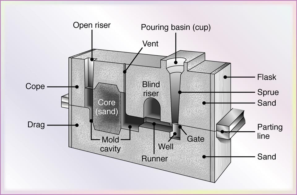
Cope and drag in Sand Mold :


Cope and Drag are the two parts of the casting flask. Cope is the upper part and drag is the lower part. Even if the casting process is flaskless , the same terms are used for the upper ans lower parts. Generally the flask is made of wood or metal. It contains molding sand. When metal is poured into the mold cavity the flask supports the mold.


Gating system:


If the molten metal is poured directly from the ladle , it will erode the bottom of the mould cavity. So molten metal is poured from the ladle to the cavity through a gating system. The gating system in casting creates a series of channels through which molten metal reaches the cavity. Gating system has -

  • Pouring Basin : It receives the molten metal from the liquid metal container. 
  • Sprue : Pouring cup is attached to the sprue. It is vertical in shape . On the other part of the sprue there is part called runner. 
  • Sprue Base : Its the base of the sprue
  • Runner : It is the horizontal part of the gating system. It connects the spues with the gates. 
  •  The next part is the choke. 
  • Then comes the skim bob 
  • Gates and ingates : It controls the movement of the metal from the runners into the cavity. 
  • Riser 

sand mold features

different parts of sand mold


Riser:

The risers are also known as feed heads. When the metal solidifies it starts to shrink. And then risers comes into play. These feeder supply metals to the cavity when shrinking of the metal starts. 

sand mold gating system for a horizontal plating mold


sectional view of a sand mold


Core:

Cores are required to create the castings with holes. It can be made of refractory materials. Most often core sand is used to make it. Metal cores are also available but less frequently used. 


Chaplets:

Chaplets are the supports for the cores. These are needed particularly when the cores are very big. Usually metal pieces are used to support the core. Without chaplets the core can be displaced and the casting can be spoiled. These chaplets are set-up between the core and mold surface. Caution should be taken while placing chaplets. Clean, oil and moisture free pieces should be used as chaplets. 


Chills:

These are huge metal pieces used to reduce the effect of shrinkage. These increases the thermal conductivity and heat capacity. It helps in speeding up the cooling process. So thick metal parts are cooled quickly. They can be used along with the risers. 

Please read : 

Read full post »

Sand Casting Process with Diagram

16 comments
Sand casting:
In sand casting which is also known as sand molded casting, an object is produced by sand mold. The process involves pouring of the molten metal in to the mold cavity. The molten metal is then cooled to the room temperature. The metal is solidified. After cooling, the metal object is separated from the mold.  Sand casting process has its advantages and disadvantages. So care should be taken while making delicate products. 

The six  main steps in this process are - 
  • Pattern making and placing it the sand mold. 
  • Making a proper gating system in the mold. 
  • Removing the pattern. 
  • Pouring the molten metal in the mold cavity. 
  • Cooling the mold to the room temperature. 
  • Breaking the mold and getting the casting. 
Please read : A complete guide to steps involved in casting process 

Before making the mold the properties of the molding sand should be checked.  There are different types of molding sands. Each type of sand is used in molding according to the cast materials and application of the materials. Mainly Green or Natural and Synthetic Sands are used. 

Another important factor is the pattern. Different types of patterns are available . Before making patterns these thing should be kept in mind. 


sand casting process


sand casting process diagram


Production steps in sand castings:

steps in sand casting


Figure: Steps involved in sand casting. This production sequence involves casting operation and pattern and mold making. 

After removing the casting engineers should look for the casting defects. If the defects are there then it should be identified. 

Please read 


Read full post »

Electrical Discharge Machining (EDM) Principles

17 comments
EDM is a non-conventional machining technique uniquely used for cutting metals which are not possible to cut with traditional methods. EDM only works with materials which are electrically conductive. Delicate cavities and intricate contours which are difficult to produce with a grinder or other machines can be done with Electrical Discharge Machining or EDM. The cutting tool for EDM may be made of hardened too steel, titanium carbide or inconel or kovar.  

EDM is also known as "Spark Machining" . Such name has been given for the fact that it removes the metal by applying a rapid series of repetitive electrical discharges. An electrode and the work piece is used for the conducting path of these electrical discharges. A continuously flowing fluid is always flowing to flush away the little amount of material that are removed. Repetitive discharge gives the workpiece a desired shape.

Please Read :

Two primary EDM methods are

Ram EDM and
Wire EDM.

Between this two methods the main difference is found in the electrodes. In ram EDM graphite electrodes are used. These electrodes are machined in traditional tools and a special shape is given which is connected to the power source. The electrodes are also connected to a ram. When all the arrangements are ready the electrodes are fed into the workpiece. The entire process is performed under a submerged fluid bath. In Wire EDM the electrode it self is a thin wire. Specially processed brass wires are used for feeding into the material. Electrical discharges cut the w/p according to desired shape. Wire EDM is generally done while submerged in a bath of water.

Ram Electro-Discharge Machining (EDM) Process: 

Rapid recurrence of spark produced between the two electrodes (tool & w/p) controls the metal erosion. It is to be noted that the workpiece must be an electrically conducting metal. An appropriate gap is necessary which is usually approximately 0.025 to 0.075 mm known as spark gap. The gap must be maintained between the w/p and the tool by a servo motor which runs by the difference between a reference and gap breakdown voltage. The tool moves upwards and downwards by this operating motor.
The rate of metal removal depends on the spark gap. If both the electrodes are made of same materials then the highest erosion is found on the positive electrode or the anode. So logically to get a high metal removal rate and a greater tool life the tool is made as cathode and workpiece works as anode, The two electrodes are kept apart and are separated by a dielectric fluid. A transient electric discharge is found across the gap between the two electrodes in the form of spark. When the potential difference between the electrodes is sufficient, the dielectric fluid is ionized and break down which in terms produces an conductive spark channel. The current is discharged across the channel by the condensers as spark. If the potential difference is less than or equal to 12 volts the dielectric fluid is deionized. The process is repeat itself as the condensers start to recharge. The spark interval is generally 10 to 30 microseconds and the current density ranges from 15-500 am/mm2. The energy is released from the sparks in the form of local heat and eventually local temperature found is in the order of 12000°C. Such high temperature and pressure melts and erodes some metals some of which is vaporized and other fine material particles are carried by the fluid circulating around the electrodes which creates a crater on the w/p. As the time interval of the sparks is very low the heat doesn't get time to conducted between the tool & workpiece. Fig below shows a schematic diagram of the whole process.

RAM Electrical Discharge Machining (EDM)


How to choose the Tool Material
Many factors are needed to be taken into consideration while selecting the tool material.
  • Low erosion rate and decent work to tool wear ratio
  • good electrical conductivity 
  • good machinability 
  • low electrical resistance 
  • high melting point . 
  • high rate of electron emission  
EDM has one major drawback and it is the wear ratio of the tool. Different material has different wear ratio. For Brass it is 1:1 . For metallic electrodes it is found 3:1 or 4:1 . For high melting point electrode graphite it ranges from 5:1 to 50 :1 . 

Tool Wear

While applying EDM the tool or cathode also erodes which is not desirable. It is unavoidable but remains in tolerable limit as the wear of the cathode is much less than the anode. This occurs because -
  • Positive ions from the dielectric fluid hit the cathode but electrons strikes the anode. Though electrons are much lighter than the positive ions it possesses more energy as it moves it greater velocity. So anode gets more eroded. 
  • At the time of spark a compressive force is created at the cathode which reduces the cathode erosion. 
  • Fluid medium is generally hydrocarbon. Due to pyrolysis gases are produced which produces carbon particle and these particles create a thin layer of protection on the cathode. Thus the cathode is much safer than anode. 

Purpose of Dielectric Fluid 
  • Effective Coolant for the workpiece and the tool . 
  • It works as an insulating material during the charging of the condenser as a result perfect condition for efficacious spark discharge and its conduction when ionized is obtained. 
  • The eroded materials are carried away by this medium. 
  • It is a coolant in quenching the spark and prevents the arcing. 

Essential Requirements for dielectric fluid 

  • Optimum Viscosity is necessary . If the viscosity is low then the fluid will not be able to carry the metal particles. On the other hand if the viscosity is high then it will restrict the flow of the liquid. 
  • It should be non-reactive with the work piece, container or the tool material. 
  • Non-expensive, easily available and inflammable. 
  • It should not produce toxic gases or vapors during the operation. 
  • It should be a hydrocarbon compound. 
Different dielectric fluids are : transformer oil, spirit (white), oil and kerosene etc. If some conducting power like aluminum or light graphite is added to the fluid then the metal removal rate increases. 


Advantages of EDM

  • Metal having any hardness or brittleness and toughness can be machined. 
  • Harder materials such as steel alloys or tungsten carbides which are used for molding and other non-conventional machining like forging and press tools can be reproduced. 
  • Dies can be machined at hardened condition. 
  • Complicated shapes can be reproduced. 
  • Very fine holes can be done very accurately . 
  • The accuracy is very high. Tolerance of 0.005 mm can be achieved. 
  • Wear resistance surface can be made because workpieces produced with EDM have micro-craters which can contain lubricants effectively. 
  • The physical contact between the tool and w/p is avoided. No cutting force other than blasting pressure is exerted. So fragile jobs and cylinders can be machined without causing any damage. 
  • Harder metals can be machined very quickly in comparison to the conventional machining process. 

Disadvantages Electrical Discharge Machining 

  • The power required for machining is much higher compared to the conventional machining. (120J/mm2)
  • There are chances of surface cracking when the materials become brittle at room temperature. 
  • A thin layer usually ranging from 0.01 mm to 0,10 mm containing 4 % carbon may be deposited on the workpieces made of steel 
  • The Material Removal Rate  (MRR) is comparatively low (75 mm3/sec)
  • Reproducing sharp corners is difficult in EDM. 
  • Sometimes the micro-structures are distorted and subsequently etching occurs. 


Applications of EDM 

Generally EDM is hugely used for machining burr free intricate shapes as well as narrow slots and blind cavities. Sinking of dies , plastic molding, die casting compacting, cold heading, extrusion, press tools, wire drawings are some of the examples of its application. Negative tool geometry can also be generated on a w/p if suitable tool can be made. EDM is very useful for machining small holes. It is also used to cut slot in diesel fuel injection nozzles. It is also used in air crfat engines and brake valves etc.


Wire Electrical Discharge Machining

A very thin wire of diameter ranging from 0.02 to 0.3 mm is used as an electrode in wire cut EDM. It cuts the workpiece with electrical discharge just like a band saw. In this process either workpiece or the wire is moved. The spark discharge phenomenon is used for eroding the metal which is same as the conventional EDM. In wire cut EDM the wire acts as an electrode as a result complicated shapes can be cut easily without forming electrode. Basically the wire-cut EDM consists of a machine which has a workpiece contour movement control unit ( NC tension : a power supply which supplies electrical energy to the wire and has a unit ) . It also has workpiece mounting table and a wire driver section. The wire driver section is use for moving the wire accurately at a constant tension. Another important part is the dielectric fluid (distilled water) supplier having constant specific resistance. Wire EDM has the following features -   
  •  No forming electrode is necessary. 
  • electrode wear is very negligible. 
  • Smooth machined surface. 
  • Tight geometrical and dimensional tolerances . 
  • Extremely high tolerances between punch and die. Extended die life. 
  • Straight holes are possible to produce. 
  • Machine can be operated without any regular supervision for long time at high operating rates. 
  • No skill is needed to run the machine. 
Wire Cut EDM

Advantages

  • Because of the absense of the split lines in the die, savings of the stages in the sequential tools occurs. It permits more punch opening per stage. 
  • There will no flashes on the molded parts because the molds with draught  can be arranged without vertical divisions. 
  • To necessity for tool manufacturing and storing. 
  •  Workpieces are hardened before cutting . So no heat treatment distortion is not present. 
  • Whole work is done in one machine . So die manufacturing cycle time is short. 
  • Lesser inspection time because of single piece construction of dies with high accuracy. 
  • Time is utilized perfectly as the wire cut EDM can cut throughout the day. 
  • Very economical even for small batch production. 
  • low thermally affected zone. High surface finish. 
  • Number of rejected workpieces are very small. 


Please Read : 

Read full post »

Mild steel - Properties of Mild Steel (Mechanical Properties)

64 comments
Mild steel is the most commonly used steel. It is used in the industries as well in the different everyday objects we use. Even the pans and spoons of the kitchen are sometimes made of mild steel. The main target of this article is to discuss about different mild steel properties. The mild steel is very important in the manufacturing of metal items. Almost 90% steel products of the world is made up of mild steel because it is the cheapest form of steel.  

Read: Mechanical Properties of Materials 


What is mild steel? 


Mild steel is the most widely used steel which is not brittle and cheap in price. Mild steel is not readily tempered or hardened but possesses enough strength. 


Mild steel Composition  


Mild steel contains - 
carbon 0.16 to 0.18 % (maximum 0.25% is allowable)
Manganese  0.70 to 0.90 %
Silicon maximum 0.40% 
Sulfur maximum 0.04% 
Phosphorous maximum 0.04% 

Mildest grade of carbon steel or mild steel contains a very low amount of carbon - 0.05 to 0.26% 


Importance of knowledge of mild steel properties 


The use of mild steel is huge and a person who is into manufacturing or production business need to know a lot about the important characteristics of mild steel. 
The study of mild steel becomes more significant for a student of mechanical engineering or metallurgical engineering. Mild steel is an alloy. And alloy is a product made by mixing metals and non metals. Sometimes a pure metal cannot fulfill all the properties needed for manufacturing product. So additives are included in the pure metal to obtain some specific properties necessary for the production. Mild steel is made by adding carbon and other elements in the iron. These elements improve the hardness, ductility and tensile strength of the metal.   


Most Important Mild Steel Properties


  • A small amount of carbon makes mild steel to change it properties. Different amount of carbon produces different types of steels. There are small spaces between the iron lattice. Carbon atoms get attached to this spaces and makes it stronger and harder. The harder the steel the lesser the ductility. 
  • The modulus of elasticity calculated for the industry grade mild steel is 210,000 Mpa. It has a average density of about 7860 kg/m3. 
  •  Mild steel is a great conductor of electricity. So it can be used easily in the welding process. 
  • Because of its malleability, mild steel can be used for constructing pipelines and other construction materials. Even domestic cookwares are made of mild steel. It is ductile and not brittle but hard. 
  • Mild steel can be easily magnetized because of its ferromagnetic properties. So electrical devices can be made of mild steel. 
  • Mild steel is very much suitable as structural steel. Different automobile manufacturers also use mild steel for making the body and parts of the vehicle. 
  • Mild steel can be easily machined in the lathe, shaper, drillling or milling machine. Its hardness can be increased by the application of carbon. 
  • Mild steel is very much prone to rust because it has high amount of carbon. When rust free products are needed people prefer stainless steel over mild steel. 
Most important Mild steel Properties
Image courtesy : http://waqarsteel.com/


I hope this compilation of mild steel properties will help the people involved in the manufacturing process as well as the engineering students. 


.
Read full post »

Solar Concentrator Classification: Advantages of Solar Concentrator

4 comments

Introduction: Definition of Solar Concentrators:


Solar Concentrator is a device which concentrates the solar energy incident over a large surface onto a smaller surface. The concentration is achieved by the use of suitable reflecting or refracting elements, which results in a increased flux density on the absorber surface compared to that existing on the concentrator aperture. In order to get a maximum concentration an arrangement for tracking the sun’s virtual motion is required.  An accurate focusing device is also required. Thus a solar concentrator consists of a focusing device, a receiver system and a tracking arrangement. Temperature as high as 3000 degrees Celsius can be got from a solar concentrator. So they have potential applications in both thermal and photovoltaic utilization of solar power at high temperatures.
Solar concentrating devices have been used for a long time. In Florence as early as 1695, a diamond could be melted by solar energy. Lavoisier carried out a number of experiments with his double-lens concentrator. The knowledge concentrator dates back even time of Archimedes, whose book "On Burning Mirrors" is an evidence of this fact. Many uses of concentrators were reported in the eighteenth and nineteenth centuries, particularly in heat engines and steam production. The advantages of concentrator are as follows: 

Solar Concentrator Classification: Advantages of Solar Concentrator

The advantages of solar concentrator


1. It increases the intensity by concentrating the energy available over a large surface onto a smaller surface (absorber)
2. Due to concentration on a smaller area, the heat loss area is reduced. Further, the thermal mass us much smaller than that of a flat plate collector and hence transient effects are small.
3. The delivery temperatures being high, a thermodynamic match between the temperature level the task occurs.
4. It helps in reducing the cost by replacing an expensive large receiver by a less expensive reflecting or refracting area.

Disadvantages of Solar Concentrator


However, concentrator is a optical system and hence the optical loss terms become significant. Further it works on beam component of solar radiation, resulting in loss of diffuse component. Although the basic concepts of flat plate collectors are applicable to concentrating systems, a number of complications arise because of non-uniform flux on absorbers, wide variations in shape, temperature and heat loss behavior of absorbers and finally the optical considerations in the energy balance conditions. It may be noted that higher the concentration of the collector, higher is the precision of optics and more is the cost of the unit. In addition to the complexity of the system, the maintenance requirements are also increased.

Classification of solar concentrator


Solar concentrators may be classified as (i) tracking type and (ii) non-tracking type. Tracking may be continuous or intermittent and may be one-axis or two -axes. As the sun may be followed by moving either the focusing part or receiver or both; concentrators can be classified accordingly. Further the system may have distributed receiver or central receiver.
The concentrators may also be classified on the basis of optical components. 
They may be 

1. Reflecting or refractory type
2. Imaging or non-imaging type
3. Line focusing or point focusing type

The reflecting or refracting surface may be one piece or a composite surface, it may be a single stage or two stage type system and may be symmetric or asymmetric. In practice however hybrid and multistage systems, incorporating various levels of the features, occur frequently.

Types of solar concentrators


There are a number of methods by which the flux radiation on receivers can be increased. Some of them have been discussed here:

   Tracking Concentrators classification: 


   Tracking Concentrators can be further classified as


    Concentrators with one axis tracking 

    These are used to achieve moderate concentration. A few of them have been described below.

i.    Fixed Mirror Solar Concentrator (FMSC)
ii.  Cylindrical Parabolic Concentrator
iii.  Linear Fresnel Lens/reflector
         (Follow the link of one axis tracking concentrator for getting the description of all three concentrators)

Concentrators with two-axes tracking 

           In order to achieve a high concentrators for high temperatures solar processes, concentrators with double curvatures are used. These requires two axes tracking of the sun. Some of these have been described below: 

i. Paraboloidal dish concentrators 
ii. Central Tower Receivers 
iii. Circular Fresnel Lens 
iv. Hemispherical bowl mirror

Non-tracking concentrators classification 

These are classified as follows: 

i. Flat Receiver with booster mirror 
ii. Tabor- Zeimer Circular Cylinder 
iii. Compound Parabolic Concentrator 
Read full post »

Industrial Engineering and Production Management Questions and Answers Part 5

0 comments
Here are some basic questions and answers about Industrial Production Engineering Hope these will help the students of IPE and Mechanical Engineering This is the part 2 of the series of questions. New posts with new questions will be posted regularly. Thanks . And comment in the respective sections for any query about mechanical engineering.  If you want the explanation of the answers then you are very much welcome to contact me through the contact us section. Cheers !

Read These : 
Industrial Engineering and Production Management Questions and Answers Part 1
Industrial Engineering and Production Management Questions and Answers Part 2 
Industrial Engineering and Production Management Questions and Answers Part 3
Industrial Engineering and Production Management Questions and Answers Part 4
Industrial Engineering and Production Management Questions and Answers Part 6

Industrial Engineering and Production Management Questions and Answers 


1. How to calculate The allowed time for a job ? 
ans- Standard time + policy allowance . 

2. How many fundamental hand motion is involved in micromotion study ? 

ans- 16. 

3. There are three activities in a PERT network on critical path. The mean times are 3,8 and 6. The standard deviations are 1,2 and 2 respectively. What is the probability that the project will be completed in 20 days ? 

ans- 0.84 

4. Scheduling determines what ? 

ans- Programme needed for the operation. 

5. A system of organisation was introduced by F. W. Taylor . It is known as - 

ans- Functional organization. 

6. What is the sequence of phases in value engineering ? 

ans- 1. creative phase 2. information phase 3.  investigation phase and 4. evaluation phase. 

7. When valve analysis is appreciated ? In large production scale or small production scale? 

ans- In large production scale. 

8. What are the conditions for using conveyors for transportation ? 

ans - loads should be uniform , no variation the routs and continuous movement of the material. 

9. Planning and scheduling of Mass production manufacturing differs from that of job order manufacturing . True or False ? 

ans - True . 

10. What information does scheduling gives us ? 

ans - The perfect time for starting the job and the amount of work that should be completed in a certain amount of time. 

11. Which type of layout is used for manufacturing steam turbine ? 
ans- fixed position layout, 

12. What information does Gantt chart give us ? 
ans- Information about production scheduling. 

13. When materials are checked in perpetual inventory control ? 
ans- when material reaches its minimum value. 

14. Why merit rating is used ? 
ans - To evaluate workers performance in a work. 

15. Do you think that acceptance sampling is good for mass production ? 
ans- Yes. 

16. What is Queuing theory  ? 
ans - It is the theory for determining the waiting times and queue lengths by using mathematical study. It is basically the study of waiting lines .  

17. What is the standard time for a job ? 
ans - delay contingency allowance plus the total work content time. 

18. What is the full form of PERT ? 
ans - Programme Evaluation and Review Technique

20. When bonus is paid to a worker in wage incentive system  named Emerson's efficiency plan ? 
ans - when his or hers output efficiency exceeds 67%. 


Thanks. These Questions will be helpful as these can be the practice questions for mechanical engineering job interview.

Industrial Engineering and Production Management Questions and Answers

Read full post »

Industrial Engineering and Production Management Questions and Answers Part 1

0 comments
Here are some basic questions and answers about Industrial Production Engineering. Hope these will help the students of IPE and Mechanical Engineering. This is the part 1 of the series of questions. New posts with new questions will be posted regularly. Thanks . And comment in the respective sections for any query about mechanical engineering.  If you want the explanation of the answers then you are very much welcome to contact me through the contact us section. Cheers !

Read These :
Industrial Engineering and Production Management Questions and Answers Part 2  
Industrial Engineering and Production Management Questions and Answers Part 3 
Industrial Engineering and Production Management Questions and Answers Part 4 
Industrial Engineering and Production Management Questions and Answers Part 5
Industrial Engineering and Production Management Questions and Answers Part 6

Industrial Engineering and Production Management Questions and Answers 

1. In Time study , Why the rating factor is applied ? Ans - fixation of incentive rate


2. Why Gantt Chart is used ? Ans - for production scheduling. 


3. What is the main purpose of value engineering ? ans - to minimize the cost without changing the quality of the product. 


4. Why Scientific Layout is used ? Ans - Minimizing production delay, increasing floor area and ensuring production quality. 


5. What Work study involues ? 
Ans -  work measurement and method study . 

6. Why A-B-C analysis is used ? 
Ans - For Inventory Control 

7. Which class of items are generally large in number in In A-B-C analysis ? 
Ans - C . 

8. PERT analysis depends on - 
Ans - Optimistic, Pessimistic and most likely time. 

9. Why Process layout is used ? 
Ans- for avoiding excessive multiplication of facilities. 

10. What is an element of Queuing Theory ? 
ans - Waiting time. 

11. What PERT requires ? 
ans- triple time estimate.

12. According to break even analysis, how total cost is got ? 
ans- by summing fixed cost and variable cost. 

13. When Bar Chart is more appropriate to use ? 
ans- for minor works. 

14. For an activity how Probabilistic time is calculated ? 
ans - By optimistic, pessimistic and most likely time. 

15. Where Line organization is suitable ? 
ans - for small organization.  

Thanks. These Questions will be helpful as these can be the practice questions for mechanical engineering job interview. 


Read full post »
 

Copyright © Mechanical Engineering Design by Free CSS Templates | Blogger Theme by BTDesigner | Powered by Blogger